| Book |
Page |
Context |
 |
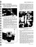 |
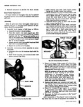
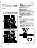
ASSEMBLY OF TRANSMISSION 1 1 Position reverse inhibitor body fig 6D 48 in transmission case on its dowel pin and secure with two screws and lockwashers Be sure to install plunger in inhibitor body PLUNGER ...
SHIFT REVERSE FINGER INHIBITOR a Fig 6D 48 Reverse Inhibitor and Shift Finger Installation 2 Coat selector shaft with grease then insert through seal from the inside of the case Do not install shaft from ...
seal lips 3 Attach shift finger to selector shaft using two bolts and lock tabs fig 6D 48 Bend tabs onto bolt heads after tightening bolts then install drain plug in case at rear |
|
 |
similar to that described I un er Wormshaft Seal Replacement J 5822 1 z Fig 4 48 Removing Bearing Cup W rmshaft Bearing Cup Replacement 1 Remove wormshaft bearing cups using Tool J5822 with Tool ...
48 2 Press new bearing cups into position using Tool J 755 fig 4 49 Bi 1 Nut Assembly Ulow procedure outlined in 500 700 and 900 Secti a Note however that the ball ...
used in the S rtswagon and commercial steering gear has 54 balls ir tead of 48 St ering Gear Assembly fig 4 50 Mter a major service overhaul where all of the origin l factory |
|
 |
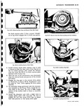
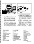
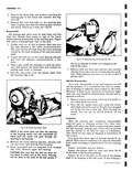
tire fig 3 47 Retract metal tube with continuous clockwise turning and pulling action fig 3 48 Do not pull but trim off excess of rubber plug protruding from puncture The repair is now complete ...
immediate use 1 wppr 0 Fig 3 47 Applying Remainder of Cement with Plug Inserted Fig 3 48 seating Plug to Complete Repair 9 Clean your tools Especially remove hardened rubber cement before using |
|
 |
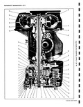
Valve Body Ditch Plate 31 Stator 46 Valve Body 47 Oil Pick up Pipe 32 Turbine 48 Low Servo Piston 33 Engine flex Plate 49 Low Servo Piston Cushion 34 Stator Cam Race Spring |
|
 |
48 |
|
 |
rrchment 8 12 ft tbs tear Housing 20 30 4t tbs to R H 42 48 ft tbs iapter 9 15 ft lbs Nitch 45 65in tbs ng Rod 20 26ft tbs x Clamp |
|
 |
Mount Tapped i Panel Reinforcement 46 Panel Rear End Inner 47 Support Engine Mount Upper ngine Compartment 48 Panel Rear End Outer tinge lower 49 Brace Rear Cross Bar To Rear Rail Rear ngine Compartment |
|
 |
lubrication information see Body Lubrication in Section 2 x t HEAVY BODIED SEALER JI Sr Fig 10 48 Front Door Hinge Sealing of Body Hinge PillarLower Hinge Shown Upper Typical |
|
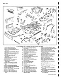 |
Inner Panel At Bumper Depression Left i Panel Reinforcement 47 Panel Rear End Inner ngine Compartment 48 Housing Rear End Panel License Plate linge Lower 49 Filler Rear End Outer Panel Right ne Compartment Cover |
|
 |
installation of door coat attaching surfaces of hinges with heavy bodied sealer as indicated in Figure 10 48 2 With aid of helper reinstall door to body opening Align hinges within marks and tighten bolts |
|
 |
LEVER STOP LEVER ASM ON BRACKET W y I ACCELERATOR LI K GE REAR Fig 9 48 Accdm CY w FORWARD ENGINE FRONT MOUNTI NG BRACKET 1 AIR CLEANER 6 l I FRTELD |
|
 |
shaft grip retainer and thrust collar and squeeze until snap ring is forced into retainer fig 8 48 Be certain shaft is not scored during this operation THRUST COLLAR a RETAINER SNAP RING |
|
 |
face plates 7 Engage the ring gear to the reverse drive plate as illustrated in Figure 6E 48 Engagement mus be made by feel while jiggling the drive plate laterally 8 On assembles being performed |
|
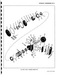 |
48 54 52 56 49 46 57 47 58 o o P 59 Pow rglide Exploded View CORVAIR SHOP MANUAL |
|
 |
same as the 500 700 and 900 Series components except as outlined in the following pages 48 Fig 3 52 Front Suspension 1200 Series kND ADJUSTMENTS ADJUSTMENT OF FRONT WHEEL BEARINGS Adjust front wheel bearings |
|
 |
48 |
|
 |
Interlock 47 Clutch Clear Roller Bearings 133 Channel Cap Front 37 Near 36 First Gear Sleeve 48 Clutch Oear Rearing 37 1 2 Synchronizer Hub 49 Clutch Gear Bearing Selective 38 Synchronizer Key Snap Ring |
|
 |
48 40 47 7 4 6 4 S 44 33 38 34 Fig 6D 13 Manual Ti 1 Clutch Shaft 16 Clutch Gear 2 Main Shaft Bearing 17 Snap Ring 3 Main Shaft Booting Retainer |
|
 |
Gear Shaft H Retaining Pin at Ring Auto Trans only J Ring Gear ans only and Speedometer 48 Axle Shaft 49 Axle Bearing Assembly cnwv tw sF1OP MANUAL |
|
 |
upper shroud assembly fig 6A 12 Turn blower and check clearance while tightening upper shroud retaining screws 48 Install fuel lines and oil level gauge Install lower engine shroud and exhaust ducts 49 Install idler |
|
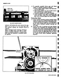 |
Install all crankcase bolts flat washers and nuts Torque the eight long bolts 7A6 20 42 to 48 ft lbs and one small bolt e 18 7 to 13 ft lbs Figure 6A 82 shows |
|
 |
Engine Assembly Engine Removed 6A 47 Crankshaft 6A 47 Camshaft 6A 47 Timing Gear Marks 6A 48 Camshaft End Play 6A 49 Timing Gear Backlash 6A 49 Flywheel and Clutch Housing 6A 49 Flywheel |
|
 |
that ball nut used in the Greenbrier and Corvair 95 steering gear has 54 balls instead of 48 Inspection With the steering gear completely disassembled wash all parts in cleaning solvent and dry thoroughly With |
|
 |
Align the grooves in the worm and nut by sighting through the ball guide holes 2 Count 48 balls into a suitable container This is the proper number of balls for this ball nut Drop |
|
 |
Turn the nut upside down and rotate the wormshaft back and forth until all 48 balls have dropped out of the nut into a clean pan With the balls removed the nut can be pulled |
|
 |
Shaft 47 Oil Pick up Pipe Attaching 31 Manual Valve Lever Screw 32 Transmission Throttle Valve 48 Low Servo Piston Retaining Clip Inner Lever 49 Low Servo Piston 33 Governor Gear Thrust Spacer |
|
 |
Lighting System 8 46 Headlamps 8 46 Replacement 8 46 Adjustment 8 46 T 3 Aimers 8 48 Aiming Screen Method 8 52 Lighting Switch Replacement 8 52 Stoplight Switch Replacement 8 52 Dimmer Switch |
|
 |
crankcase bolts must be at their specified torque Eight long bolts 7 16 20 42 to 48 ft Ibs and one 5 16 18 7 to 13 ft Ibs torque Hold bolt head on crankcase |