| Book |
Page |
Context |
 |
 |
results relative to the following data Figure 6C 53 provides gear tooth nomenclature and figure 6C 54 illustrates the various contact patterns which may be experienced FACE PITCH LINE JV FLANK BACKLASH 005 008 CLEARANCE ...
called the flank The space between the meshed teeth is referred to as backlash Figure 6C 54 shows correct and incorrect contact patterns For illustrative purposes coast side of gear contact is shown Drive ...
BACKLASH EXAMPLE D FACE CONTACT THICKER SHIM REQUIRED EXAMPLE E FLANK CONTACT THINNER SHIM REQUIRED Fig 6C 54 king Gear Contact Patterns necessary to install a thicker pinion shim as described under Pinion |
|
 |
Valve Lash Adjustment 6A 53 Oil Filter and Generator Adapter 6A 53 Spark Plugs 6A 54 Fuel Pump 6A 54 Engine Oi1 6A 54 Troubles and Remedies 6A 58 Specifications 6A 61 Special Tools |
|
 |
alignment with window lower door window and loosen ventilator division channel adjusting stud nut fig 10 54 Turn adjusting stud in or out or position lower end of channel fore or aft as required then ...
twelve to fifteen inch piece of body tape 2 or CLIP ENGAGED CLIP DISENGAGED Pig 10 54 Fron1 Deer Lock Spring Clip RETAINING PAWL CYLINDER l1 CLIP HOUSING C Fig 10 56 prow Deer |
|
 |
FRONT I i x 3 4 FORK 1 2 FORK Fig 6D 54 Shift Forks Installation tially into the case The interlock end two opposite notches of the shaft goes to the rear ...
case Engage 1 2 shift fork fig 6D 54 which is identified by the thru gate at the shift location with the 1 2 synchronizer Align the pin holes in the shaft and fork then |
|
 |
gauge measures between high spots on the points instead of the true point opening fig 8 54 Contact ACTUAL MW OPENING 021 z I t 016 FEELER GAUGE Mg 8 54 inaccurate Gauging of Rough |
|
 |
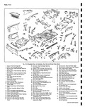
54 a 20 55 58 d J 53 5 08 1 Fig 10 104 Exploded View Underbody h 1 Support Heat Exchanger Bait 20 Extension Rear 2 Cover Heat Exchanger Opening 21 Extension Heaf ...
Outer Panel 52 Bar Rear Cross artmenf Front 53 Roil Front Compartment Cross ront Compartment Pan 54 Rail Assembly Front Compartment Pon Side artmenf Rear SS Spacer and Plate Front Compartment rss lower Pan Side |
|
 |
54 56S 1e 55 58 59 03 53 80 61 57 4j Fig 10 3 Exploded View of Underh 1 Support Heat Exchanger Bolt 22 Extension Heat 2 Cover Heat Exchanger Opening Cover Support ...
Left Upper 52 Panel Rear End Outer artment Front 53 Rail Front Compartment Cross ront Compartment Pan 54 Rail Assembly Front Compartment Pan Side artment Rear 55 Spacer and Plate Front Compartment iss Lower |
|
 |
removed or installed and bring press ram in direct contact with stud shank or head fig 3 54 Be sure that head is in full contact with hub flange when installation is completed NOTE Both |
|
 |
54 |
|
 |
Ramp Inlet and Exhaust Opening 0056 14 long Closing 0070 28 long Super Turbo Air Inlet Opens 54 BTC Closes 118 ABC Exhaust Opens 95 BBC Closes 78 ATC Tappet Lift Inlet and Exhaust |
|
 |
54 |
|
 |
area 197 9 sq in Distribution of Braking Effort theoretical On front wheels 46 On rear wheels 54 Brake Linings Material Full molded asbestos composition Width front and rear 1 75 Thickness 160 Length |
|
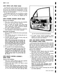 |
spring clip use a screwdriver or other suitable tool to slide clip out of engagement Figure 10 54 shows door lock spring clip engaged and disengaged LOCK CYLINDER ASSEMBLY FRONT DOOR Removal and Installation |
|
 |
wait Fig 4 54 Idler Lever Installation 1 Assemble idler to frame member torquing bolts to 15 22 ft lbs 2 With dust cap and seal in place position ball stud in relay rod boss |
|
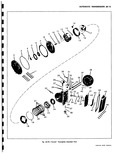 |
54 52 56 49 46 57 47 58 o o P 59 Pow rglide Exploded View CORVAIR SHOP MANUAL |
|
 |
Bushing 53 Clutch Drum Selective Thrust 39 Rear Pump Wear Plate Washer 40 Reverse Piston Outer Seal 54 Clutch Drum Bushing 41 Planet Carrier Input Sun Gear 55 Front Pump Body Bushing |
|
 |
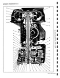
components already installed 16 Install a new square cut seal ring in front pump cover fig 6E 54 then position front pump cover dip bolt heads in oil impervious sealer such as used on Turboglide |
|
 |
54 |
|
 |
AB9N I 9 54 Lift engine with chain sling off of engine stand Tool J 5856 and onto Tool J 7894 mounted on a lifting jack Remove chain and adapter from rear mounting bracket Fuel |
|
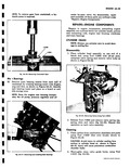 |
carbon from combustion chambers and ports using Tool J 8358 fine wire brush shown in Figure 6A 54 CAUTION Avoid injury to cylinder sealing face surface in cylinder head as shown in Figure |
|
 |
lPSll Condition R N D L Disconnect TV rod at carburetor and vacuum hose 0 0 52 54 66 77 at balance tube Depress accelerator to W O T By disconnecting TV rod at carburetor |
|
 |
operation two 4 Install all grease fittings and lubricate with chassis grease Idler Arm Assembly fig 4 54 When defective condition is indicated by excessive play in the pivoting joints or by apparent damage |
|
 |
Note however that the ball nut used in the S rtswagon and commercial steering gear has 54 balls ir tead of 48 St ering Gear Assembly fig 4 50 Mter a major service overhaul where |
|
 |
Section Note however that ball nut used in the Greenbrier and Corvair 95 steering gear has 54 balls instead of 48 Inspection With the steering gear completely disassembled wash all parts in cleaning solvent |
|
 |
54 Pressing Stud Front Hub C BUSHING LOWER CONTROL ARM i s MS 3 55 Frent Pivot Height sa 16 under this heading with the following operations 1 Check Inflate nt height may be checked |
|
 |
Overall Width 70 0 in Wheelbase 95 0 in Turning Diameter 42 6 ft Load Compartment Height 54 0 in Length 106 2in Width 59 4 in Side Loading Doors |
|
 |
Shaft Rear Bushing Spring Seat 38 Converter Assembly 53 Low Servo Piston Shaft 39 Converter Hub Bushing 54 Relief Ball Spring Retainer 40 Rear Pump and Reverse Piston 55 Low Servo Piston Return Spring Assembly |