
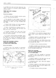
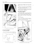
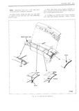
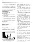
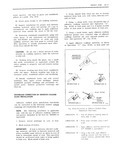
adjuster from seat assembly Fig 1H22 Fig4 II I2O FI m Bucket Sem Beck Attochmcnl 63339 SIyIeI 54 To install reverse removal procedure


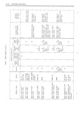

| Book | Page | Context |
|---|---|---|
|
|
tainer Fig 1H20I securing inner and outer seat r IHS back arm to seat cushion pins 54 Carefully diseaigage seat back arms from FIg IH2I B kEI Sem A IIUSI r seat cushion pins ... adjuster from seat assembly Fig 1H22 Fig4 II I2O FI m Bucket Sem Beck Attochmcnl 63339 SIyIeI 54 To install reverse removal procedure |
|
|
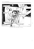
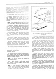
54 1 V W 4 S M W A j i wnr 1 0w necumrony V Q ATTACHING scnews V 4 V mom ounce LOWER VV re W Amusrmc sruusir |
|
|
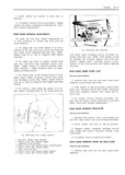
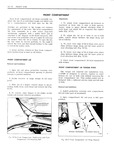
proper alignment as described in Rear REGULATOR Door Window Adjustments 1 t it H 1 t 54 KDOOR LOCK I scREws REAR DOOR WINDOW ADJUSTMENTS I I To make any rear door window adjustments |
|
|
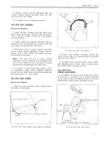
ESCUTCHEON 1 GASKET VIEW IN CIRCLE A ELECTRlC WEW N URCLE A lM U Ll ll 54 Fig 4F2l Tail Gate Window Regulator Assembly TAIL GATE WINDOW 2 Disengage lock cylinder case and switch |
|
|
Fe2FlI III II rr s I Y I Q rrr 54 I ANI I I 2 i ILIIiT II TIL iYIf II I I Q V J RUN QHANNEL5 I II I I I i1iT |
|
|
Zwrr M 1 1 e 1 s1 11 1 g W Jl 1H ll 1 n 54 1 I A II I1 1 I 9 j SPRING |
|
|
54 E X 4 V Em 5 E 2 O 4 U E 5 v 2 u 3 U GRY 4 W QOEE |
|
|
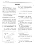
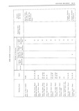
gage hole at center of kick up F1 4 area Ref Dimension Location 54 3 32 j 13 7 8 Lower surface of compartment St 1RW 1 Sedan Sz pan side rail spring support |
|
|
changes UI any Ilme wIII 0ul n0I I te 4L I Aucusr 19 54 FISHER BODY DIVISION GENERAL MOTORS CORP |
|
|
54 g A5 ew 5 A5 WE i3 Zim 56 w 4 5v q D 4 S4 E 5 27mm Ima U1 ZC 0 4 2m Aimq |
|
|
54 |
|
|
NOTE Dimvnsiun nut vary 1 1 After buck 54 Pkmn new buck vurtziin win l w nsseinhly nn curtain his hven r niiipiet ljc instgilhad v1 in w vez eci work bench with |
|
|
sliding glass fore and afti L l i i szcdira SEC MA 54 With sliding window partially open use a flat bladed tool to disengage pry snap in rosebud fasteners on lower glass rLm channel |
|
|
IE92 Fig 5 I 53 Front Root Roil Wedge Plate Fig 5 I 54 Front Roof Rail Adjustment |
|
|
girl 4 Eg e 5E 5g wa mam Dia ZO OC BSI14 rI 4 4 m4 54 |
|
|
rear roof 4 bow should also be sealed using neoprene type weatherstrip adhesive i ra l 54 When completed folding top should be free HM from wrinkles and draws Install all previously removed trim |
|
|
mission and relay assembly to new parts mmese 34 Remove nut securing relay to support and l 54 To install reverse removal procedure Check lemove re dy hom wat isbembly seat adjusters for proper operation |
|
|
REAR END and primer furnished in GM Kit Part No 4226000 54 Using a small brush apply adhesive caulking OF Q iV21i t material primer over trimmed edge of adhesive caulking material and over adjacent |
|
|
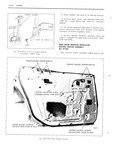
54 DOORS I FRONT GUIDE 3 Raise window and prnp it in fu1l up positiem I 2I I wII I II I IIr 7 II I 4 Re ni ve inner panel ram utt11PI1i11gb |
|
|
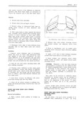
justable it is imperative that replacement door lasses be installed flush with the guidexlates 54 1 1 1 g 4 T0 lmtd l revel be Hmmm pmcecure at the front and rear of the glass |
|
|
open position FRONT COMPARTMEN1 Merr itt A LID TO HINGE sous j TORQUE R ODS V 1 54 |
|
|
applied to both sides of tteflector lf anew water deflector is to be installed use old water 54 Place Striku and uuustmn plates Within deflector as a template and trim new deflector to Scribe marks |
|
|
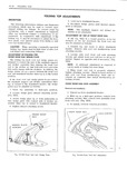
unsatisfactory the hook on the lock assembly may be adjusted as Fig 2 I 54 Wedge Plate Insrollerion follows |
|
|
PMME 23 Install windshield lower and side reveal g V moldings then upper reveal moldings Install 54 I 4 7 windshield garnish moldings and previously re V L J moved parts Remove protective coverings |
|
|
glass to fill W LL the void NOTE Glass handling suction cups may be used TAPE 54 when removing or installing the windshield glass AD E5 vE FROM EDGE CAULKING MATERIAL 15 Watertest windshield immediately |
|
|
54 |